Variant 2 - Propping of the cantilevering panels at the middle point
Operating with assembling tool and personal fall-arrest system
Ground rules
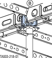
The Dokadek edge head 18mm is used for making a platform up to 1.0 m wide at the building edge with cantilevered Dokadek panels. In this configuration the Dokadek edge head 18mm supports the Dokadek panel at the middle, not at the one-third point.
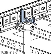
Close-up of Dokadek edge head 18mm
|
Used at panel joint |
Used with panel and infill beam |
|---|---|
|
|
|
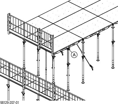
Practical example
|
A Dokadek edge head 18mm |
|
B Pin for fixing the edge head on the panel (included with product) |
Permitted platform load p [kN/m2] on cantilevered panel (see table)
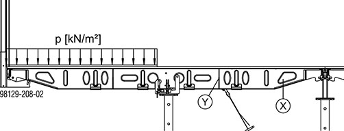
Permitted concrete load on cantilevered panel
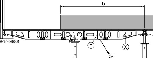
b ... max. 140 cm
|
X 1st grip hole |
|
Y Bulkhead plate at one-third point |
|
|
Variant 1 |
Variant 2 |
|---|---|---|
|
Load Class 1. as defined in EN 12811 |
Load Class 2. as defined in EN 12811 |
|
|
|
Permitted platform load p ≤ 0.75 kN/m2 |
Permitted platform load p ≤ 1.50 kN/m2 |
|
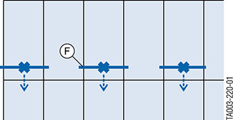
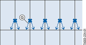
Attachment to grip hole |
In this configuration, a scaffold tube 1.50m has to be tied back from the 1st grip hole in every second panel. Make sure that each scaffold tube is correctly positioned: The scaffold tube has to tie back the adjacent panel as well. |
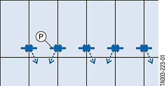
In this configuration a tie-back is required in the form of a scaffold tube 1.50m or a short tie rod 20.0 in the 1st grip hole at every joint between two panels. Make sure that the lashing straps are installed to left and right alternately. |
|
|
|
|
Max. back-stay force: 3.00 kN |
Max. back-stay force: 5.00 kN |
|
|
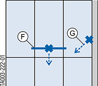
Attachment to bulkhead plate |
If necessary (for example close to the wall), the panel can also be tied back by means of the bulkhead plate at the one-third point. |
Alternatively, each panel can also be tied back twice by means of the bulkhead plate at the one-third point. |
|
|
|
F Scaffold tube 48.3mm 1.50m |
|
G Lashing strap 5.00m |
|
P Tie rod 20.0 or Scaffold tube 48.3mm 0.50m |
Permitted slab thickness [cm] without additional precautions
|
Panel size |
Permitted slab thickness |
Deflection |
|---|---|---|
|
1.22x2.44m |
30 |
Line 6 |
|
1.22x2.44m |
> 30 - 32 |
Line 5 |
|
0.81x2.44m |
45 |
Line 6 |
|
0.81x2.44m |
> 45 - 50 |
Line 5 |
|
|
NOTICE ▪ This method must not be used for constructing outward-staggered floor-slabs. ▪ It is not possible to change the direction of the panels at the structure edge. ▪ The outermost row of floor props must be at a distance of at least 10 cm from the slab edge. ▪ The last row of floor props with support heads must be at a distance of 140 cm from the structure edge, so that the edge head 18mm can be installed centred underneath the cantilevered panel (platform width ≤ 1.0m). |

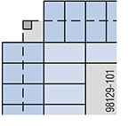
Diagrammatic floorplan
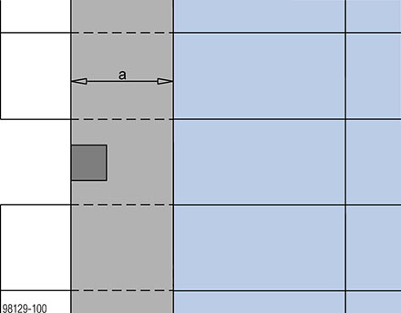
a ... 140 cm
|
|
|
Dokadek panels on lower level |
|
|
|
slab between two levels |
|
|
|
Dokadek panels on upper level |
.
Closing the formwork
|
|
WARNING ➤ Before stepping on to the panels at the slab edge (which will act as the platform), make sure that the floor props with the Dokadek edge heads 18mm on the level below are not stress-relieved! |

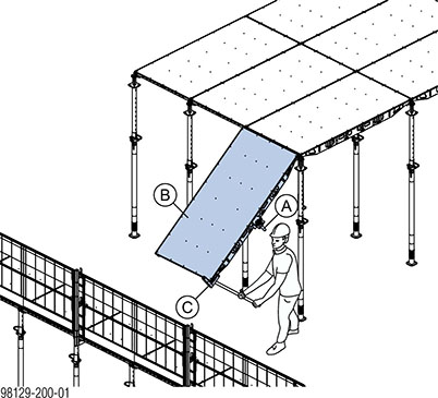
➤ Mount the Dokadek edge head 18mm and the Dokadek handrail-post shoe short on the Dokadek panel.
➤ Engage the Dokadek panel in the heads and use the assembling tool to lift the free end up to the horizontal.
|
A Dokadek edge head 18mm |
|
B Dokadek panel |
|
C Dokadek handrail-post shoe short |
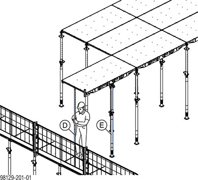
➤ Secure the assembling tool so that it cannot fall and pin the floor prop into the Dokadek edge head 18mm with Spring locked connecting pins 16mm.
|
D Dokadek assembling tool B |
|
E Doka floor prop Eurex |
|
|
WARNING Risk of panels tipping over! ➤ Do not remove the assembling tool until after the tie-back has been installed and secured! |
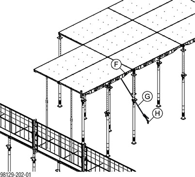
➤ Mount the next panel in the same way. If necessary, mount handrail post shoes on the Dokadek panel.
➤ Install tie-backs in accordance with the platform load (see the section headed ‘Ground rules’.
|
F Scaffold tube 48.3mm 1.50m |
|
G Lashing strap 5.00m |
|
H Doka express anchor 16x125mm |
➤ Mount further panels in the same way. If necessary, mount handrail post shoes on the Dokadek panel.
|
|
WARNING ➤ No-one is allowed to step on to the formwork area before all safety measures have been compiled with and all panels and infill areas securely stayed. ➤ Use appropriate personal fall-arrest system equipment when installing the handrail posts and protective gratings! |
|
|
NOTICE ➤ The lashing straps are allowed to be temporarily released while the panels are being levelled. However, the lashing straps may only be released one at a time. |
➤ Level the panels.
➤ Mount Handrail posts XP and Protective gratings XP on the formwork.
➤ Install infill zones and lay intermediate panels in position.
.
Mounting fillers between the cantilevering panels
|
|
WARNING ➤ Secure cantilevered slab formwork to prevent lift-out and tipover. ➤ Secondary beams with stop-end formwork must be secured against horizontal pull-out. ➤ In addition, if necessary, put up a protection platform on the structure (e.g. Folding platform K). ➤ Use spring cotters to secure the infill beams to the heads. |
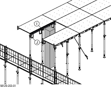
➤ Engage Infill beams 2.44m in the heads and secure each infill beam with spring cotters to prevent lift-out.
➤ Hook 4 suspension clamps into the infill beams as close to the floor props as possible. Hook 2 suspension clamps into the infill beam, in the outermost position.
|
I Dokadek infill beam 2.44m |
|
J Dokadek suspension clamp H20 |
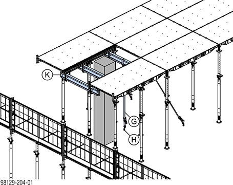
➤ First engage the inner primary beam in the suspension clamps.
➤ Pass the lashing strap round the primary beam and tie it back vertically with an express anchor.
➤ Then engage the remaining two primary beams.
|
G Lashing strap 5.00m |
|
H Doka express anchor 16x125mm |
|
K Doka beam H20 used as primary beam (e.g. 1.80m) |
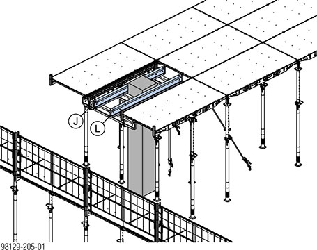
➤ Mount Doka beams H20 as secondary beams.
|
J Dokadek suspension clamp H20 |
|
L Doka beam H20 used as secondary beam (e.g. 2.45m) |
|
|
To make the sheets easier to strip, it is recommended to nail them to the infill beams only. |

➤ Mount the fillers.
Close-up plan view
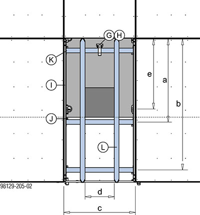
|
|
Designation |
Dimensions [cm] |
|---|---|---|
|
a |
Position of middle primary beam |
153 |
|
b |
Position of outer primary beam |
224 |
|
c |
max. infill width without centred |
≤ 122 |
|
d |
Max. spacing of secondary-beams |
depends on form-ply |
|
e |
Position of floor prop with main beam head |
122 |
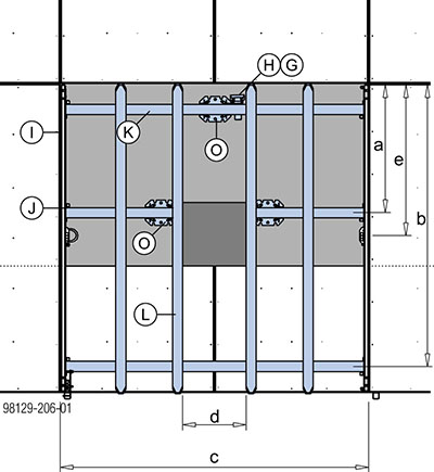
Close-up of floorplan, column at joint between two panels
|
|
Designation |
Dimensions [cm] |
|---|---|---|
|
a |
Position of middle primary beam |
as close as possible to the middle of the column |
|
b |
Position of outer primary beam |
224 |
|
c |
Max. infill width (1 centred extra prop at the rear primary beam) |
≤ 244 |
|
d |
Max. spacing of secondary-beams |
depends on form-ply |
|
e |
Position of floor prop with main beam head |
122 |
|
G Lashing strap 5.00m |
|
H Doka express anchor 16x125mm |
|
I Dokadek infill beam 2.44m |
|
J Dokadek suspension clamp H20 |
|
K Doka beam H20 used as primary beam (e.g. 1.80m) |
|
L Doka beam H20 used as secondary beam (e.g. 2.45m) |
|
O Doka 4-way head |
.
Pouring
|
|
WARNING Ensure correct direction of pouring! ➤ Always work outwards from the middle of the building towards the edge of the slab when pouring. |
Permitted slab thickness [cm] without additional precautions
|
Panel size |
Permitted slab thickness |
Deflection |
|---|---|---|
|
1.22x2.44m |
30 |
Line 6 |
|
1.22x2.44m |
> 30 - 32 |
Line 5 |
|
0.81x2.44m |
45 |
Line 6 |
|
0.81x2.44m |
> 45 - 50 |
Line 5 |
To protect the surface of the form-facing, we recommend using a vibrator with a protective rubber cap.
|
|
PU foam (e.g. Hilti CF-FW 500 or Würth UNI PUR) can be used to seal any gaps between the formwork and the walls. 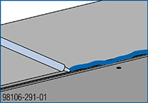
|
.
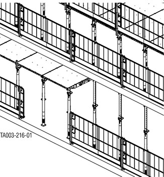
Stripping out the formwork
|
|
NOTICE ▪ Comply with the stipulated stripping times. ▪ Observe the following sections in the 'Panel floor formwork Dokadek 30' User Information booklet. - ‘Reshoring props, concrete technology and stripping’ - If necessary, 'Additional precautions for slab thicknesses of up to 50 cm'. |
|
|
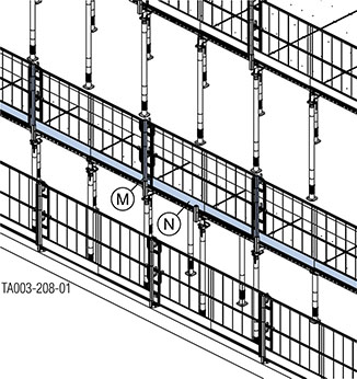
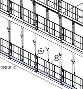
WARNING ➤ The panels at the slab edge must remain in place (see illustration). |
➤ Move the guardrail system back from the slab formwork to the edge of the structure.
|
M Handrail post XP |
|
N Protective grating XP |
➤ Put up temporary reshoring in the infill zone.
➤ Strip the infill zone.
|
|
NOTICE ➤ Use appropriate personal fall-arrest system equipment when removing the guardrail system. |
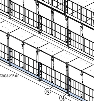
➤ Remove the guardrail system at the edge of the structure in the area of the panel to be stripped out.
|
M Handrail post XP |
|
N Protective grating XP |
|
|
NOTICE ➤ Always comply with the country-specific safety regulations! |
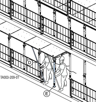
➤ Secure two adjacent panels with assembling tools and remove the corresponding floor props.
|
D Dokadek assembling tool B |
|
E Doka floor prop Eurex |
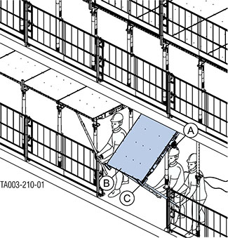
➤ Position another assembling tool underneath the panel to be stripped out. Tilt down the panel and remove the mounted parts.
|
A Dokadek edge head P 18mm |
|
B Dokadek panel |
|
C Dokadek handrail-post shoe short |
➤ Put the guardrail system back into position at the edge of the structure and disengage the panel.
➤ Disengage the guardrail system at the next panel for removal.
➤ Take down the other panels in the same way.
|
M Handrail post XP |
|
N Protective grating XP |
.