Variant 1 - Propping of the cantilevering panels at the one-third point

|
|
NOTICE Use of Dokadek panels 1.22x1.22m and 0.81x1.22m at structure edge not permitted. |

Permitted slab thickness [cm] without additional precautions
|
Panel size |
Permitted slab thickness |
Deflection |
|---|---|---|
|
1.22x2.44m |
30 |
Line 6 |
|
1.22x2.44m |
> 30 - 35 |
Line 5 |
|
1.22x1.22m |
35 |
Line 5 |
|
0.81x2.44m |
45 |
Line 6 |
|
0.81x2.44m |
> 45 - 50 |
Line 5 |
|
0.81x1.22m |
50 |
Line 6 |
.
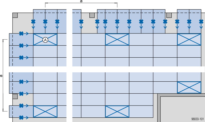
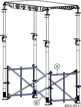
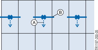
Schematic set-up
1) Erect formwork in the typical zone until only the planned infill zone is left unformed; level and secure it against tip-over.
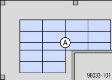
|
A Typical zone |
2) Set up the cantilevering panels, level them and tie them back.
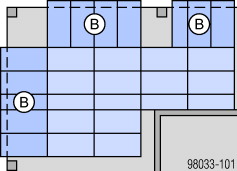
|
B Cantilevering panels |
3) Mount guardrail systems.
4) Form the infilling in the typical zone.
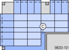
|
C Infilling in typical zone |
5) Form the infilling between the cantilevering panels.
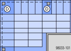
|
D Infilling between cantilevering panels |
6) Mount the stop-end formwork.
.
Dokadek heads
|
|
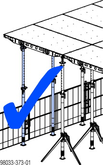
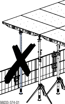
WARNING ➤ The Dokadek heads must always be fixed to the floor prop with the correct pin (exception: edge heads at a panel joint). ➤ The edge head may only be fitted to the outside one-third point of the panel. |

|
Right! |
Wrong! |
|---|---|
|
|
|
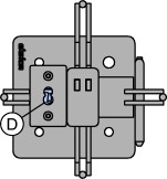
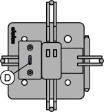
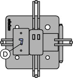
Position of the Dokadek heads
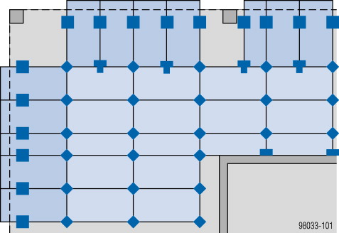
Legend
|
Support head |
Edge head |
Cross head |
Wall head |
|---|---|---|---|
|
|

|

|

|

|
|

|
|

1) |

1) 2) |

1) |

1) Spring locked connecting pin 16mm not included with product
2) Spring locked connecting pin 16mm only needed when the edge head is combined with an infill beam
|
|
NOTICE ▪ When placing the panels onto the heads, make sure that the panels are correctly fixed in the heads. ▪ Edge heads to which infill beams are mounted (in the infill zone) must be secured with Spring locked connecting pins 16mm. ▪ If a Dokadek panel 1.22x2.44m is to be connected, the cross head is fitted in the middle of the broadside of the panel. ▪ If a Dokadek panel 0.81x2.44m is to be connected, the cross head is fitted at the one-third point of the broadside of the panel. |
.
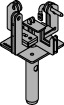
Installation examples
|
Support head |
|---|
|
|
Edge head |
|
|---|---|
|
Used at panel joint |
Used with panel and infill beam |
|
|
|
|
A Pin for fixing the edge head on the panel (included with product) |
Identification mark (D) on 'Edge head' to show matching sheet thickness
|
Sheet thickness |
||
|---|---|---|
|
18 mm |
21 mm |
27 mm |
|
|
|
|
|
Cross head |
Wall head |
|---|---|
|
Used on the broadside of the panel, at the one-third point or in the middle of the panel |
|
|
|
|
.
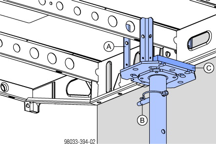
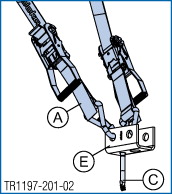
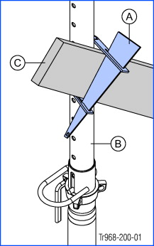
Forming wall junctions
In place of the relevant edge head at the one-third point of the panel, on wall junctions the 4-way head or Lowering head is used instead.
|
A 4-way head H20 or Lowering head H20 |
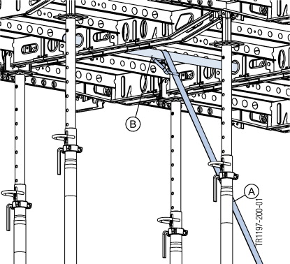
|
B Spring-locked connecting pin 16 mm |
|
C Height compensation min. 21 mm (fix with nails) |
.
Securing the formwork against tip-over
|
|
WARNING ➤ Before anybody steps onto the surface of the formwork, its stability must be ensured by e.g. wall clamps or lashing straps. ➤ Transfer of concreting loads must be ensured by other measures (e.g. by transferring these loads into the structure or using tie-backs). ➤ All cantilevered panels must be secured against overturning. |
|
|
For more information on tie-backs with lashing straps, see the section headed 'Floor formwork around edges' in the 'Panel floor formwork Dokadek 30' User Information booklet and the ‘Lashing strap 5.00m’ User Information booklet. |

|
|
NOTICE ▪ Secure every floor prop in the 1st row of props with a Removable folding tripod. - Shoring height < 3.00 m: Removable folding tripod - Shoring height ≥ 3.00 m: Removable folding tripod 1.20m ▪ While the formwork is being set up, make a braced unit on the 1st pair of panels (with removable folding tripods), every max. 7.50 m and on the last pair of panels (without removable folding tripods) – see 'Practical examples 1 & 2'. - Alternatively, tie-backs can also be attached (see Practical example 3). ▪ Important to remember when mounting the floor prop (incl. cross head): in the typical zone, secure – with tripods – the props that have only 1 panel resting on them. ▪ Tie back the typical zones at the corners. ▪ Tie back cantilevering panels: - by the Scaffold tube 0.50m on every panel joint (see Practical example 5) - additionally, on the outside panels, by the middle bulkhead plate (see Practical example 6) |
Variant with braced unit
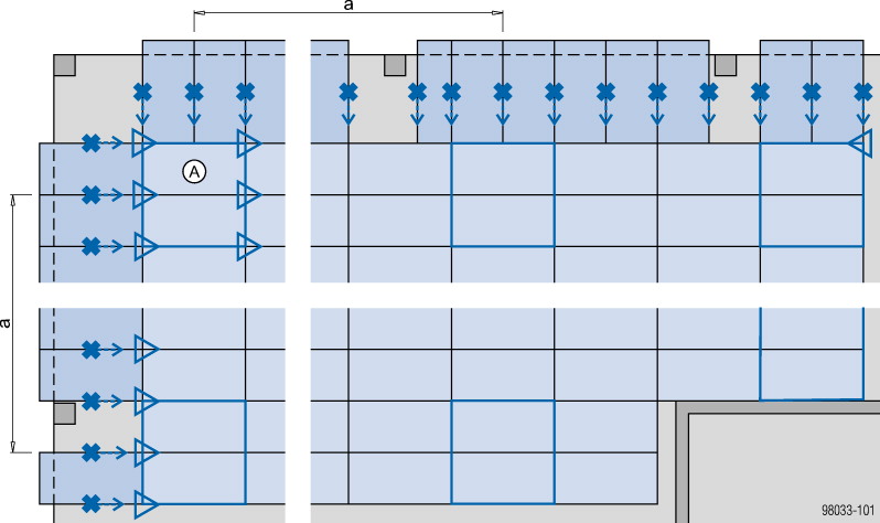
a ... braced unit on1st pair of panels, every max. 7.50 m and on the final pair of panels
|
A Starting unit |
Legend
|
|
Removable folding tripod |

|
Fixing point (e.g. with tie-back) |

|
Braced unit |

Variant without braced unit
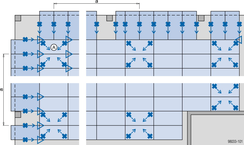
a ... braced unit / tie-back on 1st pair of panels, every max. 7.50 m and on the final pair of panels
Variant with Bracing frame Eurex
a ... braced unit with bracing frames Eurex on1st pair of panels, every max. 7.50 m and on the final pair of panels
|
A Starting unit |
Legend
|
|
Removable folding tripod |

|
Fixing point (e.g. with tie-back) |

|
Braced unit |

|
Bracing frames Eurex with diagonal crosses |

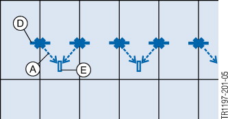
Practical example 1
Braced unit on 1st pair of panels
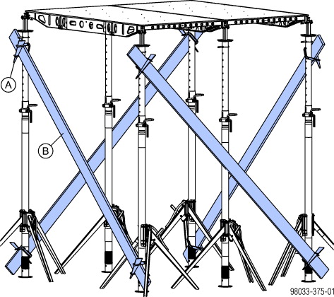
Practical example 2
Alternative braced unit
Practical example 3
Alternative tie-back
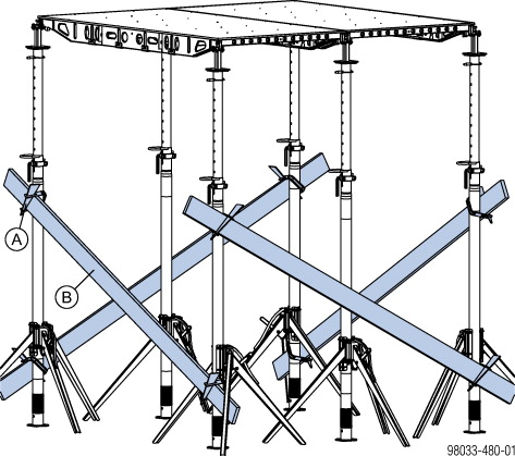
Practical example 4
With bracing frame Eurex
|
A Bracing frame Eurex |
|
B Diagonal cross |
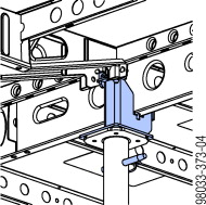
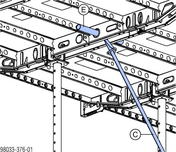
Practical example 5
Tie-back at panel joint
|
A Lashing strap 5.00m |
|
C Doka express anchor 16x125mm |
|
D Scaffold tube 48.3mm 0.50m |
|
E Bracing shoe |
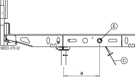
a ... 50 cm
|
Permitted bracing force in longitudinal direction on the Scaffold tube 48.3mm 0.50m: 5 kN |
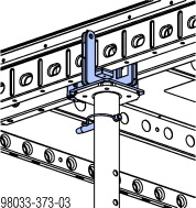
Practical example 6
Tie-back in middle bulkhead plate
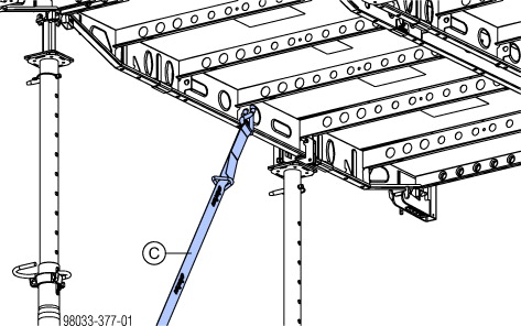
|
Permitted bracing force in longitudinal and transverse directions at the middle bulkhead plate: 5 kN |
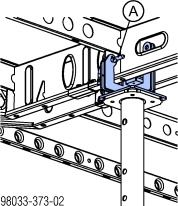
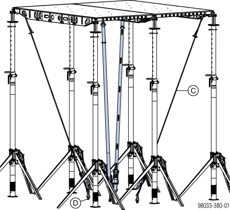
Practical example 7
Tie back at the inter-panel joint at the middle point with Dokadek plumbing strut connector
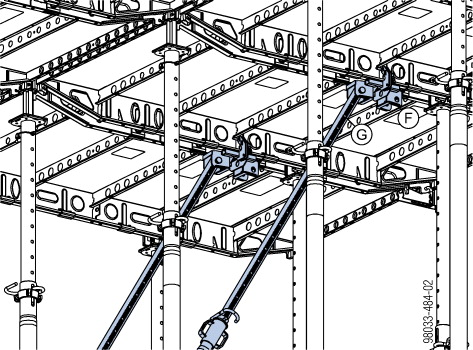
|
A Bracing clamp B |
|
B Plank |
|
C Lashing strap 5.00m |
|
D Doka express anchor 16x125mm |
|
E Scaffold tube 48.3mm 0.50m |
|
F Dokadek plumbing strut connector |
|
G Plumbing strut 340 IB or 540 IB |
|
Permitted compressive force: 13.5 kN Permitted tensile force: 5 kN |
|
|
For details on use of the Dokadek plumbing strut connector see the section headed 'Sloping slabs' in the 'Panel floor formwork Dokadek 30' User Information booklet. |
Practical example 8
Tie-back in middle of the panel
|
A Lashing strap 5.00m |
|
B Scaffold tube 48.3mm 1.50m |
|
Permitted bracing force in longitudinal direction on the Scaffold tube 48.3mm 1.50m: 3 kN |
.
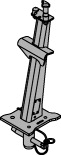
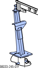
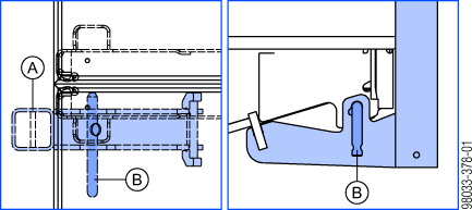
Bracing clamp B
Planks can be attached to the floor props as diagonal braces, using the Bracing clamp B.
|
|
NOTICE ▪ Only allowed to be used as a set-up aid. ▪ Not suitable for sustaining horizontal loads during pouring. ▪ Always hammer in the wedge from top to bottom! |
|
A Bracing clamp B |
|
B Doka floor prop Eurex 30 |
|
C Plank |
Possible plank/floor-prop combinations with the Bracing clamp B
|
Eurex 30 top |
Plank |
|||||||||||
|---|---|---|---|---|---|---|---|---|---|---|---|---|
|
2.4 x 15 |
3 x 15 |
4 x 15 |
5 x 10 |
5 x 12 |
5 x 15 |
|||||||
|
IT |
OT |
IT |
OT |
IT |
OT |
IT |
OT |
IT |
OT |
IT |
OT |
|
|
250 |
— |
✓ |
— |
✓ |
✓ |
✓ |
✓ |
✓ |
✓ |
✓ |
✓ |
✓ |
|
300 |
— |
✓ |
✓ |
✓ |
✓ |
✓ |
✓ |
✓ |
✓ |
✓ |
✓ |
✓ |
|
350 |
✓ |
✓ |
✓ |
✓ |
✓ |
✓ |
✓ |
✓ |
✓ |
✓ |
✓ |
✓ |
|
400 |
✓ |
✓ |
✓ |
✓ |
✓ |
✓ |
✓ |
✓ |
✓ |
✓ |
✓ |
✓ |
|
450 |
✓ |
✓ |
✓ |
✓ |
✓ |
✓ |
✓ |
— |
✓ |
— |
✓ |
— |
|
550 |
✓ |
✓ |
✓ |
✓ |
✓ |
— |
✓ |
— |
✓ |
— |
— |
— |
|
Legend: |
|
|
IT |
Inner tube |
|
OT |
Outer tube |
|
✓ |
Possible to combine |
|
— |
Not possible to combine |
.
FreeFalcon
|
|
WARNING Risk of falling at open edges! ➤ Personnel must be trained to use personal fall-arrest systems (e.g. safety harness) until all fall protection has been installed. ➤ Suitable anchorage points must be defined by an approved person appointed by the contractor. |
|
|
A fall arrester such as the FreeFalcon provides a mobile anchorage point for the safety harness. 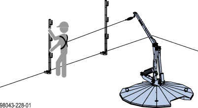
|

|
|
User instruction prior to use of the FreeFalcon is mandatory. |
.
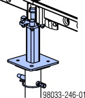
Guardrail systems on the formwork
|
|
For more information on permitted influence width of the handrail-post shoe, see the section headed 'Floor formwork around edges' in the 'Panel floor formwork Dokadek 30' User Information booklet. |
Note:
The position of the Handrail-post shoe short is different from that in the standard installation configuration as described in the 'Floor formwork around edges' section of the 'Panel floor formwork Dokadek 30' User Information booklet.
|
A Dokadek handrail-post shoe short |
|
B Bolt (vertical!) |
.
Fall-arrest systems on the structure
Note:
When tilting up cantilevering panels, make sure that these do not collide with the guardrail system on the structure. Different minimum room heights are required, depending on the attachment method used.
Possible ranges of use with Edge protection system XP
|
Attachment method used |
Min. room height 'h' |
|---|---|
|
Handrail-post shoe XP |
310 cm |
|
Railing clamp XP 40cm |
300 cm |
|
Screw-on shoe XP |
300 cm |
Note:
Always comply with the country-specific safety regulations! For lower room heights, the guardrail system can be temporarily removed and a personal fall-arrest system (PFAS) must be used instead (e.g. safety harness).
Practical example
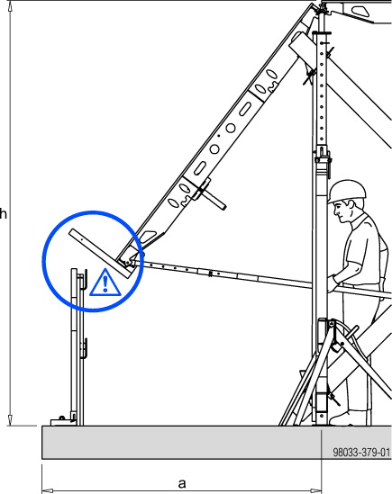
a ... 210 cm (checking is necessary for any other dimension than this!)
.