Securing the formwork against tip-over
|
|
WARNING ➤ Before anybody steps onto the surface of the formwork, its stability must be ensured by e.g. wall clamps or lashing straps. ➤ Transfer of horizontal loads as defined by EN 12812 must be ensured by other measures (e.g. by transferring these loads into the structure or using tie-backs). ➤ All cantilevered panels must be secured against overturning. |

|
|
For more information on tie-backs with lashing straps, see the section headed 'Floor formwork around edges' in the 'Panel floor formwork Dokadek 30 with drop head' User Information booklet. |

|
|
NOTICE ▪ Secure every floor prop in the 1st row of props with a Removable folding tripod. - Shoring height < 3.00 m: Removable folding tripod - Shoring height ≥ 3.00 m: Removable folding tripod 1.20m ▪ While the formwork is being set up, make a braced unit on the 1st pair of panels (with removable folding tripods), every max. 7.50 m and on the last pair of panels (without removable folding tripods) – see 'Practical example 1 - Braced unit on 1st pair of panels' & 'Practical example 2 - Alternative braced unit'. - Alternatively, tie-backs can also be attached (see 'Practical example 3 - Alternative tie-back'). ▪ Important to remember when mounting the floor prop (incl. cross head): in the typical zone, secure – with tripods – the props that have only 1 panel resting on them. ▪ Tie back the typical zones at the corners. ▪ Tie back cantilevering panels: - by the Scaffold tube 0.50m on every panel joint (see 'Practical example 4 - With bracing frame Eurex') - additionally, on the outside panels, by the middle bulkhead plate (see 'Practical example 5 - Tie-back at panel joint') |

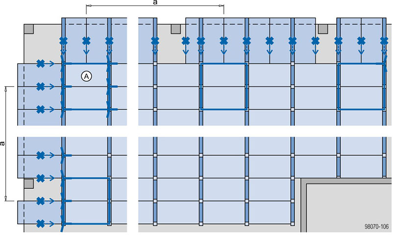
Variant with braced unit
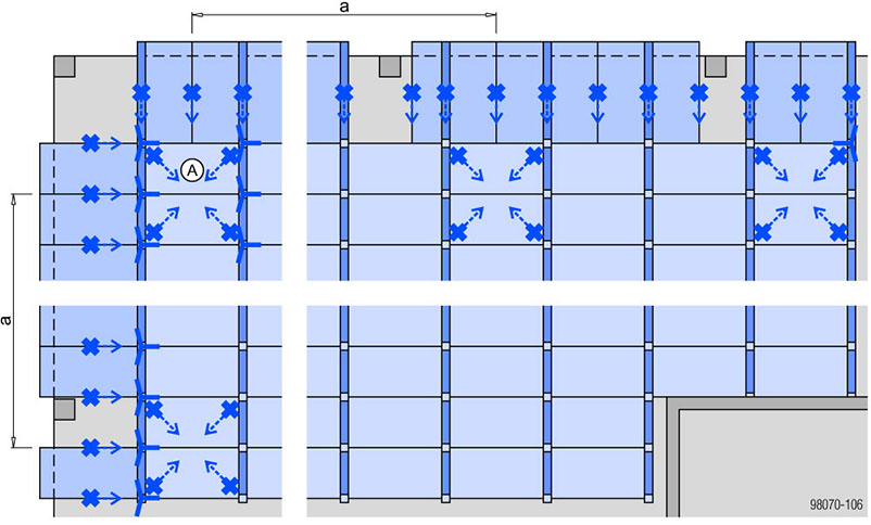
Variant without braced unit
a ... braced unit / tie-back on 1st pair of panels, every max. 7.50 m and on the final pair of panels
Variant with Bracing frame Eurex
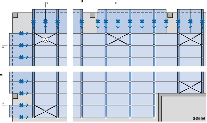
a ... every 7.50 m and on last panel
|
A Starting unit |
Legend
|
|
Removable folding tripod |

|
Fixing point (e.g. with tie-back) |

|
Braced unit |

|
Bracing frames Eurex with diagonal crosses |

.
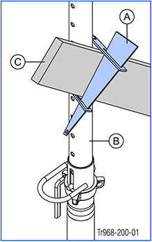
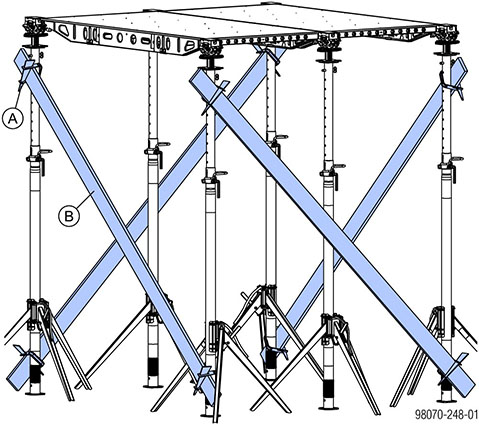
Bracing clamp B
Planks can be attached to the floor props as diagonal braces, using the Bracing clamp B.
|
|
NOTICE ▪ Only allowed to be used as a set-up aid. ▪ Not suitable for sustaining horizontal loads during pouring. ▪ Always hammer in the wedge from top to bottom! |
|
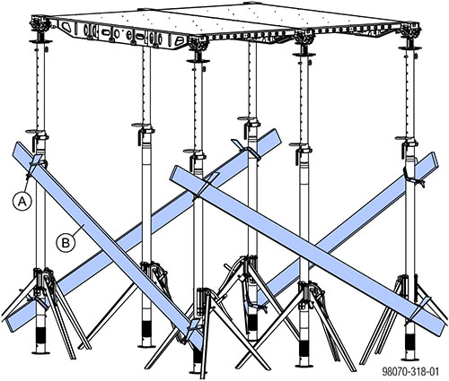
A Bracing clamp B |
|
B Doka floor prop Eurex 30 |
|
C Plank |
Possible plank/floor-prop combinations with the Bracing clamp B
|
Eurex 30 top |
Plank |
|||||||||||
|---|---|---|---|---|---|---|---|---|---|---|---|---|
|
2.4 x 15 |
3 x 15 |
4 x 15 |
5 x 10 |
5 x 12 |
5 x 15 |
|||||||
|
IT |
OT |
IT |
OT |
IT |
OT |
IT |
OT |
IT |
OT |
IT |
OT |
|
|
250 |
— |
✓ |
— |
✓ |
✓ |
✓ |
✓ |
✓ |
✓ |
✓ |
✓ |
✓ |
|
300 |
— |
✓ |
✓ |
✓ |
✓ |
✓ |
✓ |
✓ |
✓ |
✓ |
✓ |
✓ |
|
350 |
✓ |
✓ |
✓ |
✓ |
✓ |
✓ |
✓ |
✓ |
✓ |
✓ |
✓ |
✓ |
|
400 |
✓ |
✓ |
✓ |
✓ |
✓ |
✓ |
✓ |
✓ |
✓ |
✓ |
✓ |
✓ |
|
450 |
✓ |
✓ |
✓ |
✓ |
✓ |
✓ |
✓ |
— |
✓ |
— |
✓ |
— |
|
550 |
✓ |
✓ |
✓ |
✓ |
✓ |
— |
✓ |
— |
✓ |
— |
— |
— |
|
Legend: |
|
|
IT |
Inner tube |
|
OT |
Outer tube |
|
✓ |
Possible to combine |
|
— |
Not possible to combine |
.
Practical example 1 - Braced unit on 1st pair of panels
.
Practical example 2 - Alternative braced unit
.
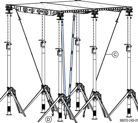
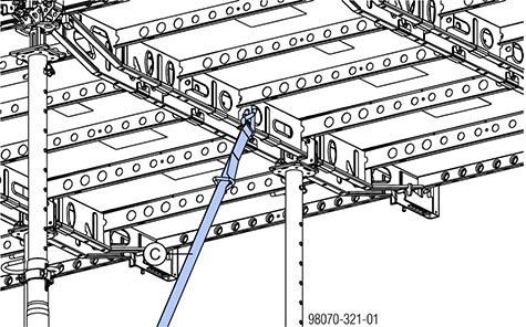
Practical example 3 - Alternative tie-back
.
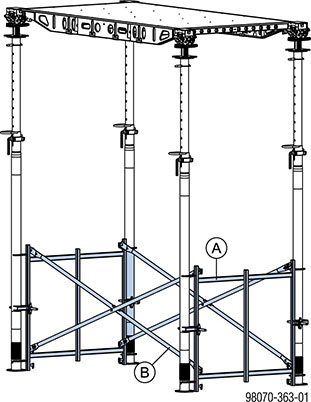
Practical example 4 - With bracing frame Eurex
|
A Bracing frame Eurex |
|
B Diagonal cross |
.
Practical example 5 - Tie-back at panel joint
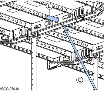
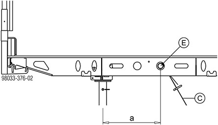
a ... 50 cm
|
Permitted bracing force in longitudinal direction on the Scaffold tube 48.3mm 0.50m: 5 kN |
.
Practical example 6 - Tie-back in middle bulkhead plate
|
A Bracing clamp B |
|
B Plank |
|
C Lashing strap 5.00m |
|
D Doka express anchor 16x125mm |
|
E Scaffold tube 48.3mm 0.50m |
|
Permitted bracing force in longitudinal and transverse directions at the middle bulkhead plate: 5 kN |
.
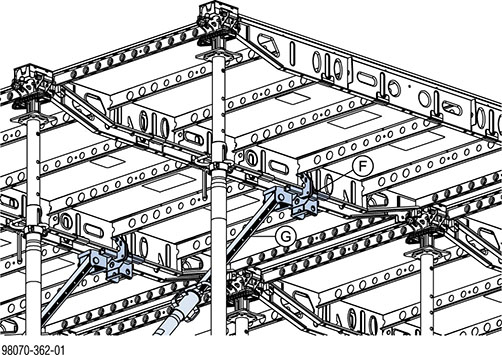
Practical example 7 - Tie back at the inter-panel joint at the one-third point with Dokadek plumbing strut connector
|
A Bracing clamp B |
|
B Plank |
|
C Lashing strap 5.00m |
|
D Doka express anchor 16x125mm |
|
E Scaffold tube 48.3mm 0.50m |
|
F Dokadek plumbing-strut connector |
|
G Plumbing strut 340 IB or 540 IB |
|
Permitted compressive force: 13.5 kN Permitted tensile force: 5 kN |
|
|
For details on use of the Dokadek plumbing strut connector see the section headed 'Sloping slabs' in the 'Panel floor formwork Dokadek 30' User Information booklet. |
.