Structural design
Structural design of the Universal suspension head
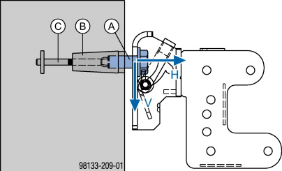
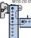
Imposed loads
|
A Cone screw M30 SW50 7cm |
|
B Universal climbing cone 15.0 2G |
|
C Stop anchor 15.0 (lost anchoring component) |
|
Imposed loads with Universal climbing cone 15.0 2G H ... permitted horizontal load: 60 kN Note the restrictions in the sections headed 'Permissible load combination of V and H' and 'Other possible anchorages'! |
|
|
NOTICE When making project-specific platforms, observe the following points: ▪ Position brackets as symmetrically as possible and keep their cantilever short. ▪ Ensure that all loads are applied centrally. ▪ The stability of the platforms must be ensured during all phases of the construction work! |

|
|
CAUTION Risk of platforms tipping over when loads are applied eccentrically. If it is unavoidable to extend a cantilever to one side, observe the following points: ➤ Choose the widest possible bracket spacing in relation to the cantilever! ➤ Allow for the greater influence on the bracket in the cantilevering region! ➤ Contact your Doka technician for information on further measures to prevent platforms tipping over. The anti-liftout guards are not suitable for sustaining planned forces! The anti-liftout guard is only designed to prevent the platform from being accidentally lifted out of its suspension point while work is in progress. |

.
Permissible load combination of V and H
Multi-purpose waling WS10 and WU12
|
Ways of installing |
||
|---|---|---|
|
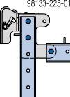
Vertical waling secured |
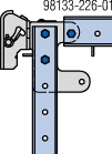
Horizontal waling secured |
|
|
Decking above waling |
Decking below waling |
|
|
|
|
|
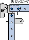
System waling pinned to the Universal suspension head |
||
|
17 kN ≤ H < 60 kN => Vperm. = 50 kN |
Vperm. ≤ 25 kN |
|
|
System waling bolted to the Universal suspension head |
||
|
Vperm. = 50 kN |
Vperm. ≤ 40 kN |
|
Connection plates on the vertical waling must always face toward the wall.
Multi-purpose walings WU14 and pairs of Channels UK12
|
Top100 tec waling WU14 1) |
Pairs of Channels UK12 |
|---|---|
|

|
|
System waling pinned to the Universal suspension head |
|
|
Vperm. ≤ 50 kN |
30 kN ≤ Vperm. ≤ 40 kN => |
|
System waling bolted to the Universal suspension head |
|
|
Vperm. ≤ 50 kN |
Vperm. ≤ 50 kN |
1) Connection plates on the vertical waling must always face toward the wall.
|
|
WARNING ➤ The Universal suspension head must be pinned to at least one waling (vertical or horizontal waling) with 2 Connecting pins 10cm and the connecting pins must be secured with 2 spring cotters. 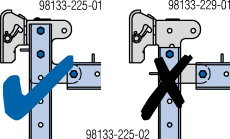
|
.